Author Information >Copyright and License information >
1Department of Cardiology, National Heart Centre Singapore, Singapore 2Department of Cardiology, National University Heart Centre Singapore, Singapore 3Department of Medicine, Yong Loo Lin School of Medicine, National University of Singapore, Singapore 4Duke-NUS Medical School, Singapore Correspondence: Dr Shen Xiayan, Senior Resident, Department of Cardiology, National Heart Centre Singapore, 5 Hospital Drive, Singapore 169609. xiayan.shen@mohh.com.sg
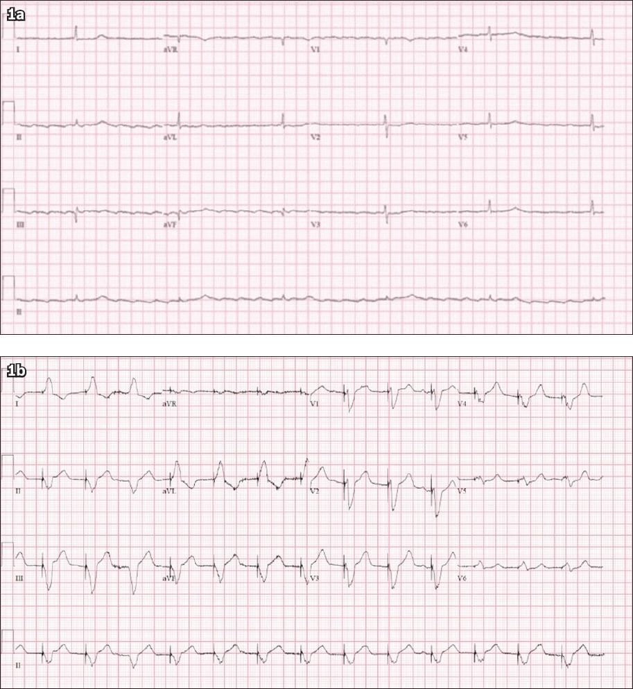
A 78-year-old Chinese man presented with lower limb swelling. He had a background of hypertension, diabetes mellitus, dyslipidaemia, chronic kidney disease and atrial flutter. He was on atenolol 25 mg for his hypertension and atrial flutter. The patient was admitted for worsening renal function and fluid overload, and was found to be bradycardic. The admission electrocardiogram (ECG) is shown in Fig. 1a. A temporary pacing wire (TPW) was subsequently inserted and the post-TPW insertion ECG is shown in Fig. 1b. What do the ECGs in Figs. 1a and b show?
Fig. 1
Case 1: 12-lead ECG (a) on admission and (b) after insertion of temporary pacing wire.
ECG INTERPRETATION
Fig. 1a shows atrial flutter with a regular R-R interval. There is a narrow-complex escape rhythm with a ventricular rate of only 36 beats per minute. The flutter waves are best appreciated as a sawtooth pattern of p waves in leads II, III, aVF and V1. Fig. 1b shows a paced rhythm after insertion of the TPW. There is a pacing spike followed by a wide-complex QRS with a left bundle branch block (LBBB)-like morphology.
CLINICAL COURSE
After TPW insertion, the patient was closely monitored for resolution of bradycardia while waiting for the atenolol to wash out. He underwent diuresis and received non-invasive ventilation for his fluid overload. The patient was no longer dependent on the TPW by Day 3 of admission and was transferred to the general ward for further management. He was subsequently discharged uneventfully and did not require permanent pacemaker insertion.
CASE 2
CLINICAL PRESENTATION
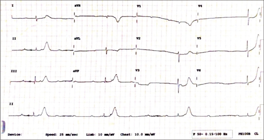
A 68-year-old Indian woman presented with giddiness and was admitted to rule out a posterior circulation stroke. Her significant past medical history included diabetes mellitus, hypertension, hyperlipidaemia and end-stage renal disease for which she was on regular haemodialysis. An ECG was done (Fig. 2). A TPW was inserted emergently, and ECGs done after insertion are shown in Figs. 3a–c.
Fig. 2
Case 2: ECG on admission of a 68-year-old woman who presented with giddiness shows complete heart block with regular P-P and R-R intervals.
Fig. 3
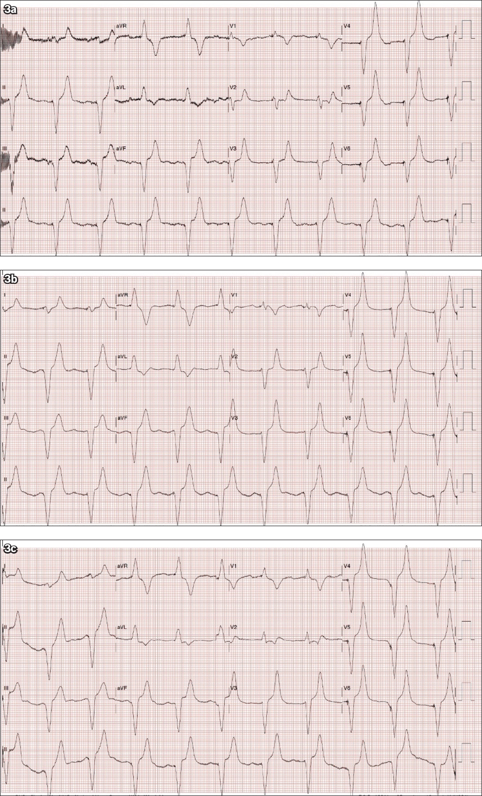
Case 2: 12-lead ECG done (a) after emergent insertion of a temporary pacing wire shows a pacing spike followed by a wide-complex QRS with a right bundle branch block-like morphology. 12-lead ECG done (b) one intercostal space down and (c) one intercostal space up.
ECG INTERPRETATION
Fig. 2 shows complete heart block with regular P-P and R-R intervals. There is a narrow-complex QRS escape rate of 21 beats per minute. The patient’s ECG post TPW insertion is shown in Fig. 3a. There is a pacing spike followed by a wide-complex QRS with a right bundle branch block (RBBB)-like morphology. Figs. 3b and c show the same findings of an RBBB morphology with the ECGs done in a ‘one space down’ and ‘one space up’ position, respectively, after TPW insertion. Although uncommon, uncomplicated right ventricular apical pacing may show an RBBB morphology.(1-4) The placement of leads V1 and V2 one intercostal space lower than standard placement usually eliminates the RBBB appearance and results in inscription of deep QR or rS complexes in V1 and V2. On the other hand, placing the leads one intercostal space higher than the usual placement enhances the height of the R wave.(1)
CLINICAL COURSE
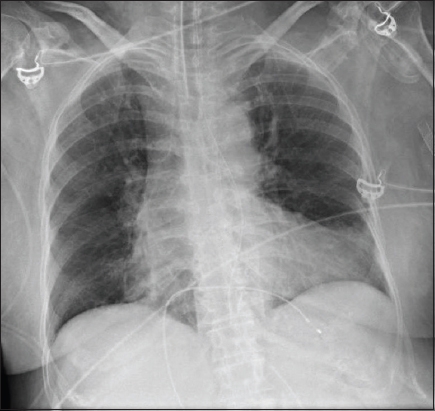
Chest radiography was performed following TPW insertion (Fig. 4). The patient subsequently underwent coronary angiography, which revealed triple vessel disease. No coronary angioplasty was done and the patient was advised to undergo coronary artery bypass grafting (CABG). The complete heart block resolved spontaneously by the second day of admission with the patient not requiring any support from the TPW thereafter. The initial complete heart block was attributed to underlying ischaemic heart disease. While awaiting the patient and family’s decision regarding CABG, the patient suffered a left middle cerebral artery infarction. Despite a thrombectomy, the patient had poor neurological recovery. The decision was made to postpone further invasive procedures in view of the poor neurological recovery.
Fig. 4
Case 2: Chest radiograph after temporary pacing wire insertion shows the placement of the wire tip within the right ventricular apex.
DISCUSSION
A third-degree atrioventricular (AV) block or complete heart block occurs when the atria and ventricles are paced independently of each other (i.e. AV dissociation) due to loss of conduction from the atria to the ventricles. In patients with sinus rhythm, the p waves are present with a regular rate faster than the ventricular rate, while QRS complexes are present with a slow and usually fixed ventricular rate. The p waves bear no relationship to the QRS complexes and the PR intervals are completely variable, as the atria and ventricles are electrically disconnected. In patients with atrial fibrillation or atrial flutter, the ventricular rate is slow and regular, as the heart relies on infranodal backup activity such as the junctional or ventricular escape rhythm, irrespective of the atrial rates. Such infranodal activity, especially the ventricular escape rhythm, can be unreliable.
The patient in Case 1 had atrial flutter and complete heart block. Under normal circumstances, the AV node in patients with atrial flutter is constantly inundated with flutter waves, resulting in a typical 2:1 or 4:1 conduction with a rapid ventricular rate. Variable blocks may also occur, resulting in an irregular heart rate. Therefore, whenever a patient with atrial flutter presents with very slow ventricular rate and regularisation of the R-R interval, the clinician should examine the ECG closely for the presence of underlying high-grade AV block (high-grade second-degree heart block or complete heart block).(5) In patients with atrial flutter, complete heart block is suspected if the heart rate becomes very slow, as demonstrated in Case 1. Similarly, the presence of complete heart block should be suspected in patients with atrial fibrillation who present with regularisation of the R-R interval.(5)
While drugs such as beta-adrenergic agonists (e.g. dopamine, epinephrine) are able to exert direct effects to enhance the junctional and infranodal escape rhythm in the setting of complete AV block, they may also result in adverse effects such as elicitation of ventricular arrhythmias and induction of coronary ischaemia, particularly in the setting of unstable coronary artery disease (as in Case 2). In addition, atropine is unlikely to improve AV block at the His bundle or His-Purkinje level.(6) Therefore, TPW insertion was chosen as the interim measure of choice over pharmacological measures in both cases.
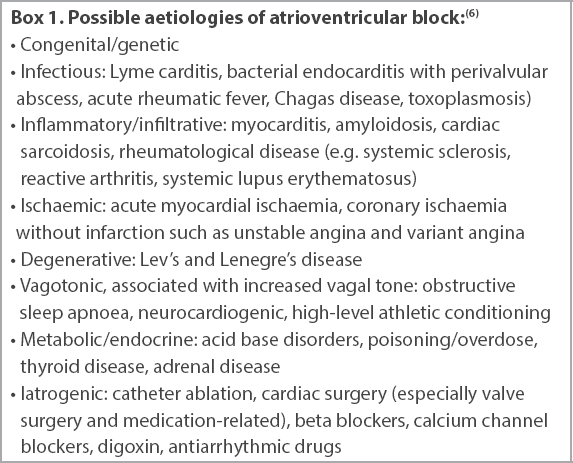
A thorough evaluation should be done to look for transient or reversible causes (Box 1) in all patients presenting with new AV block, for which treatment or resolution may make permanent pacing unnecessary. In the interim, this group of patients should have optimal medical and supportive care, including temporary transvenous pacing if necessary, before determination of the need for permanent pacing.(6) In Case 1, the patient was no longer pacing-dependent after atenolol was washed out and did not require a permanent pacemaker. It is worth noting that atenolol is almost exclusively excreted in the kidneys(7) and was previously reported to be one of the most frequently used beta blockers in patients aged above 60 years with symptomatic bradyarrhythmia.(8) It should therefore be used with caution in elderly patients with renal impairment. In Case 2, the complete heart block was attributed to underlying ischaemic heart disease. No coronary intervention was performed and the complete heart block subsequently resolved spontaneously. No further interventions were carried out for the patient due to her poor neurological status.
Box 1
Possible aetiologies of atrioventricular block:(6)
Serious complications can arise from a misplaced TPW, including systemic thromboembolism, arrhythmia and perforation.(9) In Case 2, the development of a cerebrovascular accident after TPW insertion is a major red flag and should cue the clinician to urgently determine the position of the TPW. To confirm its placement, a left anterior oblique (LAO) projection on fluoroscopy immediately after TPW insertion is useful in confirming the position of the lead.(10-13) Chest radiographs (posteroanterior and lateral), echocardiograms and ECGs are other useful adjuncts in detecting pacemaker lead malposition.(14,15)
Conventionally, the insertion of a transvenous TPW should yield an LBBB QRS pattern, as evidenced in Case 1. When an RBBB configuration appears after insertion of TPW, such as that observed in Case 2, it is imperative to rule out inadvertent left ventricular pacing through intracardiac defects such as a patent foramen ovale, a ventricular septal defect(16,17) or complications such as ventricular perforation or malposition of the pacing lead.(14,18-21) In addition, an RBBB pacing pattern can also be seen if the lead is placed in the middle cardiac vein or branches of the coronary sinus.(22)
Klein et al previously reported that eight patients whose pacing leads were located in the right ventricle apex had an RBBB pattern in leads V1 and V2.(1) The pseudo-RBBB pattern was suggested to be a result of a superior vector with depolarisation of the right ventricle preceding activation of the left ventricle, and not left-to-right septal activation. Coman et al reported seven similar cases with an RBBB pattern during permanent right ventricular pacing, with each case having pacing leads located in the distal right ventricle septum or apex.(2) In our patient (Case 2), moving the leads one intercostal space up resulted in an increase in amplitude of the R wave at V1 and V2. However, moving the V1 and V2 leads one intercostal space down did not eliminate the RBBB appearance.
In both our cases, the Q waves in lead III were larger than the Q waves in lead II. Lead III is a right-sided lead, whereas lead II is left-sided. A pacing wire placed in the right ventricle would thus cause a larger Q wave in lead III than in lead II, as the wavefront travels from right to left. In patients whose TPW is placed in the middle cardiac vein, lead II would have a larger Q wave than lead III, as the wavefront travels in a left-to-right direction.
An RBBB pattern with maximal QRS vector oriented to the right, inferior and posterior may be a warning sign of perforation of the right ventricle, whereas an RBBB pattern in right ventricular pacing with maximal QRS vector oriented to the left, superior and anterior may indicate uncomplicated right ventricular pacing.(23) Coman et al developed an algorithm to differentiate left and right ventricular RBBB pacing morphologies using frontal axis and precordial transition. When a frontal plane axis occurs between −90° and −180°, it is more likely to be left ventricular pacing, whereas if the frontal axis plane is between 0° and −90° and precordial transition occurs by V3, uncomplicated right ventricular apical pacing is said to be present with a sensitivity of 86% and specificity of 99%. In addition, a transition at V4 may indicate middle cardiac vein pacing with a sensitivity of 72% and specificity of 100%.(2) In our patient in Case 2, the frontal axis was between 0° and −90° with a precordial transition occurring by V3. By applying the criteria of Coman et al and Klein et al, as well as arranging for a chest radiograph, we determined that our pacing lead was satisfactorily placed at the right ventricular apex. The lead placement at the right ventricular apex was subsequently further confirmed on echocardiography and on computed tomography pulmonary angiography (done to rule out pulmonary embolism).
The exact mechanism of RBBB QRS morphology in right ventricular apical pacing remains unknown. However, several hypotheses have been proposed. Lister et al(24) postulated that the left ventricle may be activated first through numerous abnormal pathways when the right ventricle is paced. Mower et al(25) suggested that the pacemaker stimulus may enter the right bundle branch and then travel in a retrograde direction to the AV junction and down the left bundle branch. An alternative explanation is that the anatomical right ventricular part of the interventricular septum acts both functionally and electrically as part of the left ventricle. Meanwhile, Barold et al(26) suggested that the RBBB pattern could be due to a combination of right ventricle activation delay due to severe disease of the right ventricular conduction system and early penetration of the electrical impulse into the left ventricular conduction system.
In conclusion, an RBBB pattern on ECG following TPW insertion does not necessarily point towards lead perforation or malposition. An LAO view of the TPW on fluoroscopy after insertion, along with careful analysis of the ECG, chest radiograph and bedside echocardiogram, can facilitate recognition of the lead position in cases of doubt.
References Klein HO, Beker B, Sareli P, et al. Unusual QRS morphology associated with transvenous pacemakers.The pseudo RBBB pattern. Chest. 1985;87:517-21. Coman JA, Trohman RG.Incidence and electrocardiographic localization of safe right bundle branch block configurations dang permanent ventricular pacing.Am J Cardiol. 1995;76:781-4. Yang YN, Yin WH, Young MS.Safe right bundle branch block pattern dang permanent right ventricular pacing.J Electrocardiol. 2003;36:67-71. Jain R, Mohanan S, Haridasan V, et al. A change in QRS morphology in right ventricular apical pacing:is it a red flag sign?.Heart Asia. 2014;6:152-4. Lim Y, Singh D, Poh KK.High-grade atrioventricular block.Singapore Med J. 2018;59:346-50. Kusumoto FM, Schoenfeld MH, Barrett C, et al. 2018 ACC/AHA/HRS guideline on the evaluation and management of patients with bradycardia and cardiac conduction delay:a report of the American College of Cardiology/American Heart Association Task Force on Clinical Practice Guidelines and the Heart Rhythm Society.J Am Coll Cardiol. 2019;74:932-87. Wehling M.Multimorbidity and polypharmacy:which betablocker to use in relation to the pharmacokinetic profile and interaction potential.Arzneimittelforschung. 2010;60:57-63. Lu HT, Kam J, Nordin RB, et al. Beta-blocker use and risk of symptomatic bradyarrhythmias:a hospital-based case-control study.J Geriatr Cardiol. 2016;13:749-59. McCann P.A review of temporary cardiac pacing wires.Indian Pacing Electrophysiol J. 2007;7:40-9. McGavigan AD, Roberts-Thomson KC, Hillock RJ, Stevenson IH, Mond HG.Right ventricular outflow tract pacing:radiographic and electrocardiographic correlates of lead position.Pacing Clin Electrophysiol. 2006;29:1063-8. Mond HG, Hillock RJ, Stevenson IH, McGavigan AD.The right ventricular outflow tract:the road to septal pacing.Pacing Clin Electrophysiol. 2007;30:482-91. Mond HG.The road to right ventricular septal pacing:techniques and tools.Pacing Clin Electrophysiol. 2010;33:888-98. Hillock RJ, Mond HG.Pacing the right ventricular outflow tract septum:time to embrace the future.Europace. 2012;14:28-35. Ghani M, Thakur RK, Boughner D, et al. Malposition of transvenous pacing lead in the left ventricle.Pacing Clin Electrophysiol. 1993;16:1800-7. Mahapatra S, Bybee KA, Bunch TJ, et al. Incidence and predictors of cardiac perforation after permanent pacemaker placement.Heart Rhythm. 2005;2:907-11. Altun A, Akdemir O, Erdogan O, Aslan O, Ozbay G.Left ventricular pacemaker lead insertion through the foramen ovale--a case report.Angiology. 2002;53:609-11. Erdogan O, Altun A.Evaluation of intermittent capture in a patient who has undergone an urgent temporary transvenous pacemaker lead insertion.Postgrad Med J. 2004;80:431, 433. Mazzetti H, Dussaut A, Tentori C, Dussaut E, Lazzari JO.Transarterial permanent pacing of the left ventricle.Pacing Clin Electrophysiol. 1990;13:588-92. Meyer JA, Millar K.Malplacement of pacemaker catheters in the coronary sinus. Recognition and clinical significance.J Thorac Cardiovasc Surg. 1969;57:511-8. Ormond RS, Rubenfire M, Anbe DT, Drake EH.Radiographic demonstration of myocardial penetration by permanent endocardial pacemakers.Radiology. 1971;98:35-7. Stillman MT, Richards AM.Perforation of the interventricular septum by transvenous pacemaker catheter. Diagnosis by change in pattern of depolarization on the electrocardiogram.Am J Cardiol. 1969;24:269-73. Shettigar UR, Loungani RR, Smith CA.Inadvertent permanent ventricular pacing from the coronary vein:an electrocardiographic, roentgenographic, and echocardiographic assessment.Clin Cardiol. 1989;12:267-74. Friedberg HD.Evaluation of unusual QRS complexes produced by pacemaker stimuli--with special reference to the vectorcardiographic and echocardiographic findings.J Electrocardiol. 1980;13:409-15. Lister JW, Klotz DH, Jomain SL, Stuckey JH, Hoffman BF.Effect of pacemaker site on cardiac output and ventricular activation in dogs with complete heart block.Am J Cardiol. 1964;14:494-503. Mower MM, Aranaga CE, Tabatznik B.Unusual patterns of conduction produced by pacemaker stimuli.Am Heart J. 1967;74:24-8. Barold SS, Narula OS, Javier RP, et al. Significance of right bundle-branch block patterns dang pervenous ventricular pacing.Br Heart J. 1969;31:285-90.
REFERENCES:
1. Klein HO, Beker B, Sareli P, et al. Unusual QRS morphology associated with transvenous pacemakers. The pseudo RBBB pattern. Chest 1985; 87:517-21. https://doi.org/10.1378/chest.87.4.517
PMid:3979141
2. Coman JA, Trohman RG. Incidence and electrocardiographic localization of safe right bundle branch block configurations during permanent ventricular pacing. Am J Cardiol 1995; 76:781-4. https://doi.org/10.1016/S0002-9149(99)80226-4
3. Yang YN, Yin WH, Young MS. Safe right bundle branch block pattern during permanent right ventricular pacing. J Electrocardiol 2003; 36:67-71. https://doi.org/10.1054/jelc.2003.50002
PMid:12607198
4. Jain R, Mohanan S, Haridasan V, et al. A change in QRS morphology in right ventricular apical pacing: is it a red flag sign? Heart Asia 2014; 6:152-4. https://doi.org/10.1136/heartasia-2014-010556
PMid:27326194 PMCid:PMC4832760
5. Lim Y, Singh D, Poh KK. High-grade atrioventricular block. Singapore Med J 2018; 59:346-50. https://doi.org/10.11622/smedj.2018086
PMid:30109349 PMCid:PMC6056369
6. Kusumoto FM, Schoenfeld MH, Barrett C, et al. 2018 ACC/AHA/HRS guideline on the evaluation and management of patients with bradycardia and cardiac conduction delay: a report of the American College of Cardiology/American Heart Association Task Force on Clinical Practice Guidelines and the Heart Rhythm Society. J Am Coll Cardiol 2019; 74:932-87. https://doi.org/10.1016/j.jacc.2018.10.043
PMid:30412710
7. Wehling M. Multimorbidity and polypharmacy: which betablocker to use in relation to the pharmacokinetic profile and interaction potential. Arzneimittelforschung 2010; 60:57-63. https://doi.org/10.1055/s-0031-1296249
PMid:20329652
8. Lu HT, Kam J, Nordin RB, et al. Beta-blocker use and risk of symptomatic bradyarrhythmias: a hospital-based case-control study. J Geriatr Cardiol 2016; 13:749-59.
9. McCann P. A review of temporary cardiac pacing wires. Indian Pacing Electrophysiol J 2007; 7:40-9.
10. McGavigan AD, Roberts-Thomson KC, Hillock RJ, Stevenson IH, Mond HG. Right ventricular outflow tract pacing: radiographic and electrocardiographic correlates of lead position. Pacing Clin Electrophysiol 2006; 29:1063-8. https://doi.org/10.1111/j.1540-8159.2006.00499.x
PMid:17038137
11. Mond HG, Hillock RJ, Stevenson IH, McGavigan AD. The right ventricular outflow tract: the road to septal pacing. Pacing Clin Electrophysiol 2007; 30:482-91. https://doi.org/10.1111/j.1540-8159.2007.00697.x
PMid:17437571
13. Hillock RJ, Mond HG. Pacing the right ventricular outflow tract septum: time to embrace the future. Europace 2012; 14:28-35. https://doi.org/10.1093/europace/eur251
PMid:21846639
14. Ghani M, Thakur RK, Boughner D, et al. Malposition of transvenous pacing lead in the left ventricle. Pacing Clin Electrophysiol 1993; 16:1800-7. https://doi.org/10.1111/j.1540-8159.1993.tb01814.x
PMid:7692412
15. Mahapatra S, Bybee KA, Bunch TJ, et al. Incidence and predictors of cardiac perforation after permanent pacemaker placement. Heart Rhythm 2005; 2:907-11. https://doi.org/10.1016/j.hrthm.2005.06.011
PMid:16171740
16. Altun A, Akdemir O, Erdogan O, Aslan O, Ozbay G. Left ventricular pacemaker lead insertion through the foramen ovale--a case report. Angiology 2002; 53:609-11. https://doi.org/10.1177/000331970205300518
PMid:12365872
17. Erdogan O, Altun A. Evaluation of intermittent capture in a patient who has undergone an urgent temporary transvenous pacemaker lead insertion. Postgrad Med J 2004; 80:431, 433. https://doi.org/10.1136/pgmj.2003.011726
PMid:15254312 PMCid:PMC1743058
18. Mazzetti H, Dussaut A, Tentori C, Dussaut E, Lazzari JO. Transarterial permanent pacing of the left ventricle. Pacing Clin Electrophysiol 1990; 13:588-92. https://doi.org/10.1111/j.1540-8159.1990.tb02073.x
PMid:1693195
19. Meyer JA, Millar K. Malplacement of pacemaker catheters in the coronary sinus. Recognition and clinical significance. J Thorac Cardiovasc Surg 1969; 57:511-8. https://doi.org/10.1016/S0022-5223(19)42702-5
20. Ormond RS, Rubenfire M, Anbe DT, Drake EH. Radiographic demonstration of myocardial penetration by permanent endocardial pacemakers. Radiology 1971; 98:35-7. https://doi.org/10.1148/98.1.35
PMid:5541430
21. Stillman MT, Richards AM. Perforation of the interventricular septum by transvenous pacemaker catheter. Diagnosis by change in pattern of depolarization on the electrocardiogram. Am J Cardiol 1969; 24:269-73. https://doi.org/10.1016/0002-9149(69)90415-9
22. Shettigar UR, Loungani RR, Smith CA. Inadvertent permanent ventricular pacing from the coronary vein: an electrocardiographic, roentgenographic, and echocardiographic assessment. Clin Cardiol 1989; 12:267-74. https://doi.org/10.1002/clc.4960120508
PMid:2721040
23. Friedberg HD. Evaluation of unusual QRS complexes produced by pacemaker stimuli--with special reference to the vectorcardiographic and echocardiographic findings. J Electrocardiol 1980; 13:409-15. https://doi.org/10.1016/S0022-0736(80)80097-5
24. Lister JW, Klotz DH, Jomain SL, Stuckey JH, Hoffman BF. Effect of pacemaker site on cardiac output and ventricular activation in dogs with complete heart block. Am J Cardiol 1964; 14:494-503. https://doi.org/10.1016/0002-9149(64)90033-5